OBJECTIVES
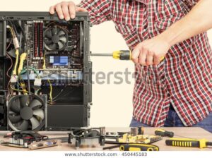
- Disassemble the PC desktop/tower Computer System
- Identification of various composite components
- Verify the correct interface cable
- Assemble the PC desktop/tower Computer System
- Boot up the System
RESOURCES
- Quality screwdriver, Tester, Soldering Iron,
- Desktop/tower Computer System
- Operating system Windows XP or higher version installed
- Utility programs
- Multimeter or AVO meter for measuring Ampere,Voltage and Ohmeter
DISCUSSION
You must start the computer to verify that it is working properly. Then Disassemble and Assemble the PC. You will go through ALL the steps of disassembling except actually taking out the drives and the Motherboard out of the system unit.
PROCEDURE (COMPUTER SYSTEM)
1.Boot up the pc (cold Booting)
(e) Put ON the PC by pushing the power button
(f) The PC will boot to Graphical users interface, Windows XP or higher version
(g) Use the path Start/Shut Down to shut down
(h) Click on Turn OFF to finally Shut Down
NOTE: the computer will shut down Windows and the power will turn off automatically.
2. IDENTIFY THE ADAPTER CARDS
(j) Unplug the power cord from the back of the PC
(k) Remove the screw on the back panel of the PC cover
(l) Take the cover or the side panel off.
Earn Free Cryptocurrency From Crypto Airdrop (Bitcoin Ethereum & More)
Join Us On Telegram Now
(m)Identify the video card. It is the one that the monitor is plugged into Removing the PC cover
(n) Write down the slots the video card is plugged into in Table 1-1.Slots are numbered from right to left starting from slot 1
(o) Identify the modem card. It is the card with the two telephone ports at the back of it.
(p) Write down the slots the modem card is plugged into in (q) Identify the network card. It is the card with the oversize phone ports. This is really a network port called RJ-45 or 10-base-T port.
(r) Write down the slots the network card is plugged into in Table 1-1
3. DISCONNECT EXTERNAL CABLES
(g) Disconnect the keyboard from the back of the computer (h) Disconnect the PS/2 or Serial mouse
(i)Disconnect the phone cable (if any )
(j) Disconnect the RJ-45 network cable (if any )
(k) Disconnect the printer cable (if any)
(l) Disconnect the monitor cable
4. DISCONNECT INTERNAL CABLE
(a) Disconnect the IDE ribbon cable from the hard drive
(b) Disconnect the IDE ribbon cable from the CD-ROM
(c) Disconnect the IDE ribbon cable from the motherboard
(d) Disconnect the FDD ribbon cable from the floppy disk drive
(e) Disconnect the FDD ribbon cable from the motherboard (f) Remove ALL the cable from the computer

5. DISCONNECT ALL Power supply connection (ASSEMBLING AND DISASSEMBLING of computer)
(a) Disconnect the power supply connector from the hard drive
(b) Disconnect the power supply connector from the CD-ROM
(c) Disconnect the power supply connector from the floppy (d) Disconnect the power supply connector from the motherboard
6. Remove the adapter card (ASSEMBLING AND DISASSEMBLING of computer)
(a) Unscrew the video card from the back panel, and then remove it
(b) Unscrew the modem card from the back panel, and then remove it
(c) Unscrew the network card from the back panel, and then remove it
7. DISCONNECT ALL front panel connections (ASSEMBLING AND DISASSEMBLING of computer)
(a) Remove the power Switch connector
(b) List the color of the wire in
(c) Remove the speaker connector (d) List the color of the wire in Table 1-2
(e) Remove the power LED connector
(f) List the color of the wire in Table 1-2 (g) Remove the hard drive channel 1 LED connector
(h) List the color of the wire in Table 1-2
(i) Remove the hard drive channel 2 LED connector
(j) List the color of the wire in Table 1-2
(k) Remove the reset switch connector
(l) List the color of the wire in Table 1-2
NOTE: Computer disassembly is now complete. Now let’s start to reassemble back the computer
8. Connecting the front panel connection (ASSEMBLING AND DISASSEMBLING of computer)
(a) Find the power LED connector and connect it to the motherboard where it is – labeled Power LED. Go to Table 1-2 if needed
(b) Find the reset switch connector and connect it to the motherboard.
(c) Find the power switch connector and connect it to the motherboard
(d) Find the hard-disk LED channel 1 connector and connect it to the motherboard
(e) Find the hard-disk LED channel 2 connector and connect it to the motherboard
(f) Find the speaker connector and connect it to the motherboard
9. Install the adapter cards
NOTE: Always make sure the cards are lined up properly with the slots. It will require a firm push to get the card to reseat on the motherboard expansion slot
(a) Install the video card into the slot recorded in Table 1-1 and screw it into the back panel
(b) Install the modem card into the slot recorded in Table 1-1 and screw it into the back panel
(c) Install the network card into the slot recorded in Table 1-1 and screw it into the back panel
10. Connect the Power Supply (ASSEMBLING AND DISASSEMBLING of computer)
NOTE: All the connectors are keyed to plug only in one way
(e) Plug the ATX or AT power connector into the motherboard
(f) Plug the power connector into the floppy disk drive
(g) Plug the power connector into the hard disk drive
(h) Plug the power connector into the CD-ROM
11. Connect the ribbon cables (ASSEMBLING AND DISASSEMBLING of computer)
(a)Connect the floppy disk drive to ribbon cable as in
(k) Connect the motherboard to ribbon cable, striped side to pin 1
(l) Connect the power cords to the PC
(m)Turn ON the PC
(n) Does the LED on the floppy turn ON immediately?
(o) Turn OFF the PC
(p) Unplug the power supply.
(q) If the answer is NO to step e above, skip to step j
(r) The cable is on backward if you answer YES to step e. Reconnect it correctly
(s) Connect the hard disk drive cable to motherboard in the primary IDE controller, striped side to pin 1
(t) Plug the middle of the connector into the hard disk drive, striped side to pin 1, and plug the end into the CD-ROM drive, striped side to pin 1
12. Connect the external cable
(a) Plug the keyboard into the lower connection. Make sure that the orientation is correct. Otherwise you can bend the pins and ruin the keyboard.
(b) Plug the mouse into the port just below or beside the keyboard as the case may be. Make sure that the orientation is correct
(c) Plug the monitor back into the video card. The connector is keyed in only one way. Make sure that the orientation is correct; otherwise you can bend the pins and ruin the monitor
(d) Plug in the power cord
(e) Replace the cover of the PC
(f) Screw in the cover screw
NOTE: reassemble is complete. You need to reboot the PC to see if it is still working properly
Finally…
13. Booting up the PC
(a) Put ON the PC by pushing the power button
(b) The PC will boot to Windows XP
(c) Use the path Start/Shut Down to shut down
(d) Click on Turn OFF to finally Shut Down


